
Note: This post carries on from Part 1.
VLANs
SW1 and SW2 have been used to allow multiple devices to connect to the VSH’s Primary, Auxiliary and lan0_0 subnets. You can either use trunk ports or access ports between the switches and R3 and R5. If using access ports, you’ll need a total of six ports per switch:
|
SW1 |
|||
| Switch Port #: | VLAN: | Connects to: | Description: |
| 1 | VLAN 2 | VSH-A Primary interface | VSH-A Primary Interface VLAN |
| 2 | VLAN 2 | R3, Fa0/0 | |
| 3 | VLAN 3 | VSH-A Auxiliary interface | VSH-A Auxiliary Interface VLAN |
| 4 | VLAN 3 | R3, Fa0/1 | |
| 5 | VLAN 4 | VSH-A lan0_0 interface | VSH-A lan0_0 Interface VLAN |
| 6 | VLAN 4 |
R3, Fa1/0 |
|
| SW2 | |||
| Switch Port #: | VLAN: | Connects to: | Description: |
| 1 | VLAN 5 | VSH-B Primary interface | VSH-B Primary Interface VLAN |
| 2 | VLAN 5 | R5, Fa0/0 | |
| 3 | VLAN 6 | VSH-B Auxiliary interface | VSH-B Auxiliary Interface VLAN |
| 4 | VLAN 6 | R5, Fa0/1 | |
| 5 | VLAN 7 | VSH-B lan0_0 interface | VSH-B lan0_0 Interface VLAN |
| 6 | VLAN 7 | R5, Fa1/0 | |
Note: The VLAN numbers align with the sub-segments mentioned previously.
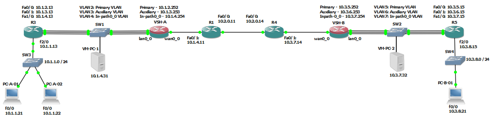
Final Diagram
Using the above IP addressing scheme and VLAN assignments, the topology looks like this:
Lab Setup
Now that the background has been explained and the IP addressing as well as the VLAN mappings have been covered, it’s time to configure the lab.
VMware Workstation
NIC Setup
This lab setup requires the use nine VMware Workstation NICs – VMnet0 through VMnet8. VMnet0 will be used to administer the ESXi host and VMnet1 through VMnet8 will be used to connect the VSH interfaces, GNS3 routers and Windows XP machines to one another.
To configure the NICs appropriately, you’ll need to do the following:
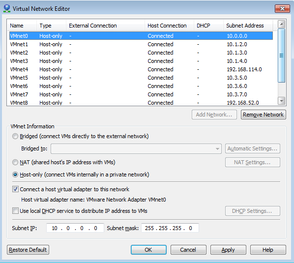
- Click on “Edit” > “Virtual Network Editor…” then configure the Workstation NICs as follows:
- Select “Host-only”Tick the “Connect a host virtual adapter to this network” box
- Untick the “Use local DHCP service to distribute IP address to VMs” box
- Configure the “Subnet IP” field of each NIC so that it aligns up with IP address plan discussed above:
| VMnet NIC: | IP Address: | Subnet Mask: | Description: |
| VMnet0 | 10.0.0.0 | 255.255.255.0 | ESXi Host Network |
| VMnet1 | 10.1.2.0 | 255.255.255.0 | VSH-A Primary network |
| VMnet2 | 10.1.3.0 | 255.255.255.0 | VSH-A Auxiliary network |
| VMnet3 | 10.1.4.0 | 255.255.255.0 | VSH-A in-path0_0 network (LAN) |
| VMnet4 | <Leave as default> | 255.255.255.0 | VSH-A in-path0_0 network (WAN) |
| VMnet5 | 10.3.5.0 | 255.255.255.0 | VSH-B Primary network |
| VMnet6 | 10.3.6.0 | 255.255.255.0 | VSH-B Auxiliary network |
| VMnet7 | 10.3.7.0 | 255.255.255.0 | VSH-B in-path0_0 network (LAN) |
| VMnet8 | <Leave as default> | 255.255.255.0 | VSH-B in-path0_0 network (WAN) |
**Note:** The description field is for your information only, you do not put it in to the NIC’s configuration.
Once completed, your NICs should look like this:
[](/assets/2015/02/netw2.png)
-
Click “OK”.
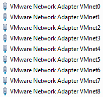
After clicking “OK”, VMware will automatically create nine new NICs on your PC and assign each of them a .1 IP address in the subnet ranges you specified. You can view the NICs by navigating to “Control Panel” > “Network and Internet” > “Network Connections”:
Note: Default gateways are not configured on these NICs, nor are they needed.
Note: The reason why VMnet4 and VMnet8’s “Subnet IP” setting were left as their default is because they must be in the same subnets as VMnet3 and VMnet7 respectively. (As mentioned previously, this is because the lan0_0 and wan0_0 interfaces are bridged, and therefore part of the same broadcast domain). However, Workstation does not allow you to put two VMnet NICs in the same subnet because if used incorrectly, it can create conflicts.
-
To work around this restriction, as mentioned above, leave the “Subnet IP” fields as their defaults. Now manually configure the NICs by navigating to “Network Connections” as described above. Once there, set the adapters the following IPs:
- VMware Network Adapter VMnet4 – 10.1.4.2 /24 – (no default gateway required)
- VMware Network Adapter VMnet8 – 10.3.7.2 /24 – (no default gateway required)
To summarise, your NIC’s IPs should look like this:
| VMnet NIC: | IP Address: | Note: |
| VMnet0 | 10.0.0.1 | Automatically configured by Workstation |
| VMnet1 | 10.1.2.1 | Automatically configured by Workstation |
| VMnet2 | 10.1.3.1 | Automatically configured by Workstation |
| VMnet3 | 10.1.4.1 | Automatically configured by Workstation |
| VMnet4 | 10.1.4.2 | Manually configured by you |
| VMnet5 | 10.3.5.1 | Automatically configured by Workstation |
| VMnet6 | 10.3.6.1 | Automatically configured by Workstation |
| VMnet7 | 10.3.7.1 | Automatically configured by Workstation |
| VMnet8 | 10.3.7.2 | Manually configured by you |
**Important:** After completing the above steps, you will need to reboot your PC. This is necessary in order to allow GNS3 to see the new NICs.
Windows XP VMs
Next, you’ll need to create a Windows XP VM. Once that VM is created, you’ll then need to clone it. This will result in you having two lab PCs.
-
Create one Windows XP VM named “VM-PC-1” and map it to the VMnet3 NIC.
- Install Windows XP.
- When the installation is completed, disable the VM’s firewall and then shut down the machine.
-
Clone the newly created VM and name it “VM-PC-2”.
Note: Cloning a VM avoids having to go through the Windows XP installation twice. You can choose either a Full Clone or a Linked Clone, it won’t matter. In the interest of conserving hard disk space though you should choose the Linked Clone option.
- Map the cloned VM’s NIC to VMnet7.
-
Start both VMs and configure them VMs with their static IP addresses:
VM: IP Address: Subnet Mask: Default Gateway: Description: VM-PC-1 10.1.4.31 255.255.255.0 10.1.4.11 VSH-A in-path0_0 network VM-PC-2 10.1.4.32 255.255.255.0 10.3.7.14 VSH-B in-path0_0 network
Doing this puts the two VMs on the same subnet as their respective VSHs, and uses R1 and R4 as the default gateways. (Refer to the “Final Diagram” above for more information).
Note: If you’d like to test connectivity, you should be able to send pings sourced from your PC and destined for the VMs and vice versa. If your pings fail in one or both directions, ensure that the firewalls are disabled on your VMs, and, if necessary, try temporarily disabling the firewall on your PC.
Note: You will not be able to ping between the two VMs at this stage. These pings will only be successful after the VSHs and GNS3 are set up.
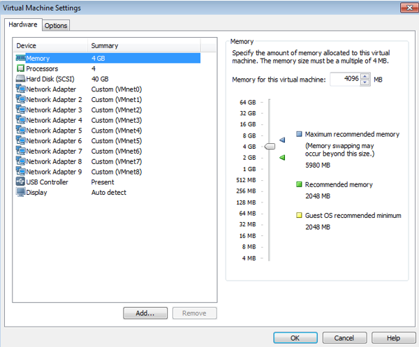
ESXi VM
Now you will need to prepare your ESXi VM.
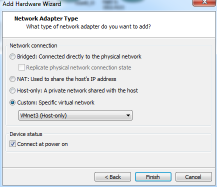
-
Map your Workstation NICs (VMnet0 through VMnet8) to your ESXi VM. Once done, the VM should look like this:
Note: If you haven’t installed ESXi in a Workstation VM before, there are plenty of step by step tutorials available on the internet.
-
After adding the NICs, boot the VM and install ESXi.
VMware ESXi
Management IP
-
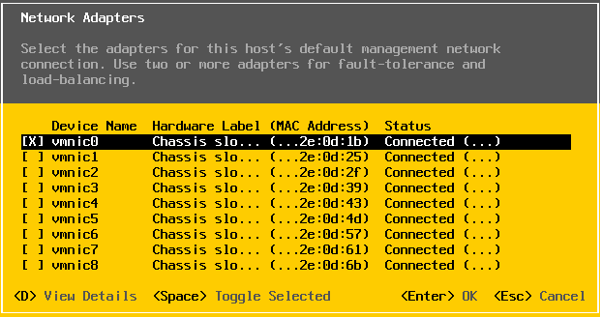
Once you’ve finished installing ESXi, you will need to configure the server’s management IP address. On the console, navigate to:
“Configure Management Network” > “Network Adapters” and select “vmnic0”.
Note: In VMware Workstation, the NICs are known as “VMnet” adapters. In ESXi, they are known as “vmnics”. Although they are named differently, their numbering is the same – e.g VMnet0 in Workstation is mapped to vmnic0 in ESXi, and so on.
-
Next, you’ll need to configure the server’s static management IP address, which is 10.0.0.251 /24.
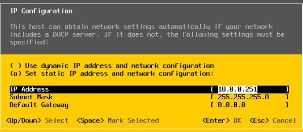
Note: A default gateway is not required because, as mentioned previously, when Workstation installed your VMnet NICs it also put them in to the correct subnets. This means that your ESXi management IP and your “VMware Network Adapter VMnet0” interface will be on the same subnet.
Note: An IPv6 management address is not required so it can be disabled.
vSphere Client
Next you’ll need to install the vSphere client software.
-
In a web browser, navigate to the ESXi host’s IP address (10.0.0.251) and then install the vSphere client by clicking on the “Download vSphere Client” link.
-
After you’ve installed the client, use it to log in to the ESXi server.
vSwitch Setup
Next you need to set up your vSwitches. By default, VMnet0 is connected to “vSwitch0” (which is called “vmware vmk”) while all other NICs are unassigned. You will need to create eight additional vSwitches and assign a single vmnic to each. To do this, complete the following steps:
-
Navigate to the “Networking” page, then click “Add Networking…” > “Virtual Machine” > “Create a vSphere standard switch”.
-
Assign the vmnics to the vSwitches and set the “Network Label” in accordance with the table below:
vSwitch: vmnic: Network Label: VLAN ID: vSwitch1 vmnic1 VSH A – Primary none vSwitch2 vmnic2 VSH A – Auxiliary none vSwitch3 vmnic3 VSH A – lan0_0 none vSwitch4 vmnic4 VSH A – wan0_0 none vSwitch5 vmnic5 VSH B – Primary none vSwitch6 vmnic6 VSH B – Auxiliary none vSwitch7 vmnic7 VSH B – lan0_0 none vSwitch8 vmnic8 VSH B – wan0_0 none Next, you’ll need to configure “Promiscuous Mode” to “Accept” for the following vSwitches:
- vSwitch3 (VSH-A’s lan0_0 interface)
- vSwitch4 (VSH-A’s wan0_0 interface)
- vSwitch7 (VSH-B’s lan0_0 interface)
- vSwitch8 (VSH-B’s wan_0 interface)
Important: This is a very important step. Not enabling “Promiscuous Mode” will result in the VSH being unable to intercept and optimise packets.
-
To enable Promiscuous mode, complete the following steps for each of the above mentioned vSwitches:
- Click on “Properties” (to the right of the vSwitch name)
- Click on the vSwitch’s name (e.g “VSH A – lan0_0”)
- Click “Edit”
- Click on the “Security” tab
- Tick all three boxes and set them to “Accept”
See Part 3 to continue.
As always, if you have any questions or have a topic that you would like me to discuss, please feel free to post a comment at the bottom of this blog entry, e-mail at will@oznetnerd.com, or drop me a message on Reddit (OzNetNerd).
Note: The opinions expressed in this blog are my own and not those of my employer.

Leave a comment