
In Part 1 & Part 2 I provided a high level overview of the UCS components. In this post I’m going to delve deeper into each of these components as well as explain how they connect to one another. When connected correctly, you’ll end up with a fully functional and fully redundant UCS system. That’s right, by fully redundant I mean there is no single point of failure anywhere in the entire system.
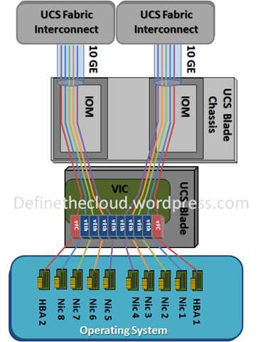
I’ll start with the “deepest” part of the system (the blades and their VICs) and then work my way “out” to the furthest part of the system, the Fabric Interconnects (FIs). It may help to keep an eye on the below diagram (taken from this Define the Cloud post) to track which part of the topology I’m talking about.
Note: As newcomers sometimes struggle with B-Series servers and the way in which data is passed between them and the UCS Chassis, most of what I write from this point on will be about these servers.
UCS Baldes
As discussed previously, there are two types of blade servers: Full Width and Half Width. Further to this though, there are also series of servers. For example, there’s the M2, M3 and M4 series. Care must be taken to ensure that you select a correctly sized server which will suit your needs, and which is also compatible with the rest of the components in your UCS system.
VIC Cards
As discussed previously, VIC cards provide the internal connectivity between the B-Series servers and the IOMs. This is required because, unlike the C-Series servers, the B-Series servers have no external ports. If you’d like to see the internal connections, you can use UCS Manager’s “Hybrid Display”:
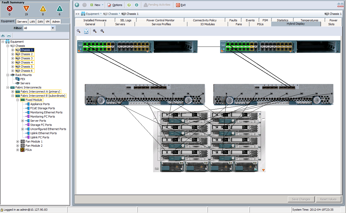
Each line between the blade servers and the IOMs (the component at the bottom and center of the diagram respectively) represents one connect between the server’s VIC and the IOM.
Note: Think of this image as a logical diagram. This is because in the diagram, the IOMs are shown to be separate/disconnected from the UCS Chassis. While it is true that they’re a separate, removable/upgradable component, in order to connect them to your system they must be physically attached to your UCS Chassis. The reason why they’re shown as a separate entity in this diagram is so that you can clearly see the internal connections between the blades and the IOMs. Finally, just in case you were wondering, the components at the top of the diagram are the Fabric Interconnects (FIs). We’ll cover those later.
Another thing to keep in mind (which I’ll expand on later) is that each VIC has at least one internal connection to each IOM. This means that by using two VICs per blade, you could suffer both a VIC and IOM failure, and you still won’t suffer any downtime. In other words, there’s no single point of failure at this layer.
Finally, as mentioned previously, the vNICs and vHBAs you create in UCS Manager are tied to your VICs. You can manually assign them to your VICs or let the UCS Manager software do it itself.
FEX/IOM
As we can see in the diagram above, the IOMs resides between the blade server’s VICs and the Fabric Interconnects (the outside world).
An important thing to note here is that each IOM connects to only one FI. In other words, IOM “A” connects to FI “A” and IOM “B” connects to FI “B”. This may seem wrong to those who’ve worked with port channels before, but it’s actually correct. In fact, if you try to connect a IOM to both FIs UCS manager will generate an error message.
This is because, as mentioned above, each blade is connected to both IOMs internally. As the IOMs connects to one FI each, this results in the blades having connectivity to both FIs. Therefore, you could suffer either a IOM or FI failure and you won’t suffer any downtime. In other words, there’s no single point of failure at this layer either.
Note: You must have two IOMs in a production environment.
Fabric Interconnect (FI)
We’ve reach the final piece of the puzzle. The FI is used to connect your blade servers to the outside world, whether that be in the form of storage, network connectivity, or most likely, both.
As mentioned previously, the FIs have the UCS Manager software installed on them. This means that in order to administer your B-Series servers, you’ll need to connect your chassis to your FIs.
Note: You must have two FIs in a production environment.
Summary
At risk of boring you, I’ll quickly summarise the above just in case you’re having a trouble understanding it. It’ll be quite similar to the one in Part 1 but with a bit more detail.
- UCS blades come in two sizes and multiple series.
- VICs are installed inside the blade and provide connectivity to the IOMs. Each VIC has at least one connection to each IOM, therefore if a IOM fails, you will not suffer downtime.
- IOMs provide the connectivity between the VICs and the FIs. As the IOMs connect each VIC in a blade, if a VIC fails you will not suffer downtime.
- FIs connect to the outside world (whether it be storage, network connectivity or both).
- As the VICs connect to both IOMs which connect to one FI each, any component can fail and you will not suffer downtime.
Other Posts in this Series
See the Cisco UCS From the Ground Up – A Beginner’s Guide – Index post for links to all of the posts in this series.
As always, if you have any questions or have a topic that you would like me to discuss, please feel free to post a comment at the bottom of this blog entry, e-mail at will@oznetnerd.com, or drop me a message on Reddit (OzNetNerd).
Note: The opinions expressed in this blog are my own and not those of my employer.

Leave a comment