
In my previous post I covered the inspiration for this series of posts as well as many of OSPF’s LSAs. Now that we’ve got the boring stuff out of the way, let’s jump into the fun stuff :)
In this post I’ll cover Type 1 and Type 2 LSAs in broadcast networks. The reason why I highlight the fact that this information applies only to broadcast networks is because, as you will see in Part 4, Type 1 LSAs are slightly different in point-to-point networks. Further to this, Type 2 LSAs don’t exist in point-to-point networks.
Let’s get started…
Broadcast Networks – Type 1 LSAs
Topology #1
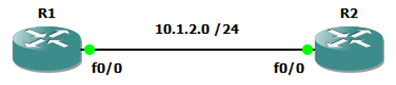
Here we have an extremely basic network. As there are two routers directly connected, it is easy to assume that they’re in a point-to-point configuration. However, as they’re using ethernet interfaces, they’re treated as broadcast by default. The reason why it is important to know this is because, as mentioned above, OSPF works differently when it’s on broadcast networks as opposed to point-to-point networks.
One such difference is that broadcast networks elect a DR and BDR. Speaking of which, in the below output we can see that R2 is the BDR. This therefore means that R1 is the DR.
R1(config-if)#do sh ip os nei

Neighbor ID     Pri   State           Dead Time   Address         Interface
2.2.2.2           1   FULL/BDR        00:00:32    10.1.2.2        FastEthernet0/0
Before going any further, let’s take another look at the Type 1 and Type 2 LSA descriptions we saw in Part 1:
-
Type 1 - Router LSA - each router announces its presence and lists the links to other routers or networks in the same area, together with the metrics to them. Type 1 LSAs are flooded across their own area only. The link-state ID of the type 1 LSA is the originating router ID.
-
Type 2 - Network LSA - the designated router (DR) on a broadcast segment (e.g. Ethernet) lists which routers are joined together by the segment. Type 2 LSAs are flooded across their own area only. The link-state ID of the type 2 LSA is the IP interface address of the DR.
R1(config-if)#do sh ip os da

            OSPF Router with ID (1.1.1.1) (Process ID 1)

                Router Link States (Area 0)

Link ID         ADV Router      Age         Seq#       Checksum Link count
1.1.1.1         1.1.1.1         345         0x80000008 0x0041BD 1
2.2.2.2         2.2.2.2         346         0x80000008 0x0003F2 1

                Net Link States (Area 0)

Link ID         ADV Router      Age         Seq#       Checksum
10.1.2.1        1.1.1.1         345         0x80000001 0x0059C2
As mentioned above, Type 1 LSAs are where “router announces its presence and lists the links to other routers or networks in the same area, together with the metrics to them”, however, above all we see is a link count (the number of links the router is advertising using the “network” command). To view details information about these links we need to use the “show ip ospf database router” command.
Before delving any deeper though, recall the following:
- The link-state ID of the type 1 LSA is the originating router ID.
- R1’s 10.1.2.1 interface is the DR for the 10.1.2.0/24 segment.
- The metric is stored in the Type 1 LSA.
- The routers only have one link each.
R1(config-if)#do sh ip ospf database router

            OSPF Router with ID (1.1.1.1) (Process ID 1)

                Router Link States (Area 0)

  LS age: 647
  Options: (No TOS-capability, DC)
  LS Type: Router Links
  Link State ID: 1.1.1.1
  Advertising Router: 1.1.1.1
  LS Seq Number: 80000008
  Checksum: 0x41BD
  Length: 36
  Number of Links: 1

    Link connected to: a Transit Network
     (Link ID) Designated Router address: 10.1.2.1
     (Link Data) Router Interface address: 10.1.2.1
      Number of TOS metrics: 0
       TOS 0 Metrics: 10

  LS age: 648
  Options: (No TOS-capability, DC)
  LS Type: Router Links
  Link State ID: 2.2.2.2
  Advertising Router: 2.2.2.2
  LS Seq Number: 80000008
  Checksum: 0x3F2
  Length: 36
  Number of Links: 1

    Link connected to: a Transit Network
     (Link ID) Designated Router address: 10.1.2.1
     (Link Data) Router Interface address: 10.1.2.2
      Number of TOS metrics: 0
       TOS 0 Metrics: 10
Topology #2
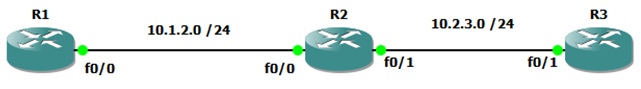
As per the diagram above, we’ve added a third router to the topology. Let’s see how this affects the output of the commands used previously:
R1(config-router)#do sh ip os da

            OSPF Router with ID (1.1.1.1) (Process ID 1)

                Router Link States (Area 0)

Link ID         ADV Router      Age         Seq#       Checksum Link count
1.1.1.1         1.1.1.1         1584        0x8000000B 0x0041B8 1
2.2.2.2         2.2.2.2         161         0x8000000C 0x00298D 2
3.3.3.3         3.3.3.3         153         0x80000003 0x0003E9 1

                Net Link States (Area 0)

Link ID         ADV Router      Age         Seq#       Checksum
10.1.2.1        1.1.1.1         753         0x80000002 0x0057C3
10.2.3.2        2.2.2.2         161         0x80000001 0x006E9E
Above we can see that R2’s link count has incremented, and that R2’s interface is the DR on the link between itself and R3.
Let’s dig a little deeper:
R1(config-router)#do sh ip ospf database router

            OSPF Router with ID (1.1.1.1) (Process ID 1)

                Router Link States (Area 0)

  LS age: 1737
  Options: (No TOS-capability, DC)
  LS Type: Router Links
  Link State ID: 1.1.1.1
  Advertising Router: 1.1.1.1
  LS Seq Number: 8000000B
  Checksum: 0x41B8
  Length: 36
  AS Boundary Router
  Number of Links: 1

    Link connected to: a Transit Network
     (Link ID) Designated Router address: 10.1.2.1
     (Link Data) Router Interface address: 10.1.2.1
      Number of TOS metrics: 0
       TOS 0 Metrics: 10


  LS age: 314
  Options: (No TOS-capability, DC)
  LS Type: Router Links
  Link State ID: 2.2.2.2
  Advertising Router: 2.2.2.2
  LS Seq Number: 8000000C
  Checksum: 0x298D
  Length: 48
  Number of Links: 2

    Link connected to: a Transit Network
     (Link ID) Designated Router address: 10.2.3.2
     (Link Data) Router Interface address: 10.2.3.2
      Number of TOS metrics: 0
       TOS 0 Metrics: 10

    Link connected to: a Transit Network
     (Link ID) Designated Router address: 10.1.2.1
     (Link Data) Router Interface address: 10.1.2.2
      Number of TOS metrics: 0
       TOS 0 Metrics: 10


  LS age: 307
  Options: (No TOS-capability, DC)
  LS Type: Router Links
  Link State ID: 3.3.3.3
  Advertising Router: 3.3.3.3
  LS Seq Number: 80000003
  Checksum: 0x3E9
  Length: 36
  Number of Links: 1

    Link connected to: a Transit Network
     (Link ID) Designated Router address: 10.2.3.2
     (Link Data) Router Interface address: 10.2.3.3
      Number of TOS metrics: 0
       TOS 0 Metrics: 10
Analysing the output above, we see the following:
- R2 is the DR for the 10.2.3.0/24 subnet. We can determine this because its “Designated Router address” and “Router Interface address” are the same.
- Details of R2’s two links.
Broadcast Networks – Type 2 LSAs
Previously I (very lightly) touched on Type 2 LSAs. Now it’s time to dig deeper.
Recall the following:
- Type 2 - Network LSA - the designated router (DR) on a broadcast segment (e.g. Ethernet) lists which routers are joined together by the segment. Type 2 LSAs are flooded across their own area only. The link-state ID of the type 2 LSA is the IP interface address of the DR.
R1(config-router)#do sh ip os da

            OSPF Router with ID (1.1.1.1) (Process ID 1)

                Router Link States (Area 0)

Link ID         ADV Router      Age         Seq#       Checksum Link count
1.1.1.1         1.1.1.1         527         0x8000000C 0x003FB9 1
2.2.2.2         2.2.2.2         929         0x8000000C 0x00298D 2
3.3.3.3         3.3.3.3         921         0x80000003 0x0003E9 1

                Net Link States (Area 0)

Link ID         ADV Router      Age         Seq#       Checksum
10.1.2.1        1.1.1.1         1521        0x80000002 0x0057C3
10.2.3.2        2.2.2.2         929         0x80000001 0x006E9E
As we saw in the Type 1 LSA outputs in the top half of this post, the output above confirms that R1’s Fa0/0 (10.1.2.1) and R2’s Fa0/1 (10.2.3.2) interfaces are the DRs for their segments.
Before we analyse the contents of the Type 2 LSA’s output, recall the following:
- The link-state ID of the type 2 LSA is the IP interface address of the DR.
- Only DR(s) advertise Type 2 LSAs.
- As mentioned above, Type 2 LSA “lists which routers are joined together by the segment”. Note that only the RID of the router(s) are listed. If you’re looking for subnet information you’ll need to look at the Type 1 LSA.
R1(config-router)#do sh ip ospf database network

            OSPF Router with ID (1.1.1.1) (Process ID 1)

                Net Link States (Area 0)

  Routing Bit Set on this LSA
  LS age: 1725
  Options: (No TOS-capability, DC)
  LS Type: Network Links
  Link State ID: 10.1.2.1 (address of Designated Router)
  Advertising Router: 1.1.1.1
  LS Seq Number: 80000002
  Checksum: 0x57C3
  Length: 32
  Network Mask: /24
        Attached Router: 1.1.1.1
        Attached Router: 2.2.2.2

  Routing Bit Set on this LSA
  LS age: 1134
  Options: (No TOS-capability, DC)
  LS Type: Network Links
  Link State ID: 10.2.3.2 (address of Designated Router)
  Advertising Router: 2.2.2.2
  LS Seq Number: 80000001
  Checksum: 0x6E9E
  Length: 32
  Network Mask: /24
        Attached Router: 2.2.2.2
        Attached Router: 3.3.3.3
Type 1 LSA + Type 2 LSA = DYI Network Diagram
In Part 3 I demonstrate how you can create an OSPF area network diagram using only Type 1 and Type 2 LSAs.
Other Posts in this Series
See the A Deep Dive in OSPF LSAs - Index post for links to all of the posts in this series.
As always, if you have any questions or have a topic that you would like me to discuss, please feel free to post a comment at the bottom of this blog entry, e-mail at will@oznetnerd.com, or drop me a message on Reddit (OzNetNerd).
Note: The opinions expressed in this blog are my own and not those of my employer.

Leave a comment